Every once and a while I need to shuffle walls and rooms around. This can cause major headaches when trying to make sure my plan remains consistent with my intended programatic area requirements. In this workflow with Revit & Dynamo, I show how I am able to visually make sure my rooms remain within a specified range of SF. You can run this node as a onetime check or better yet run it while you are updating your plan for realtime results.
Friday, September 9, 2016
Friday, July 29, 2016
Skewed Grids In Dynamo
Skewed Grids in Dynamo
 |
| Figure 1. Rectilinear Grid |
 |
| Figure 2. Skewed Grid |
Not sure why it took me so long to accomplish this because the solution was fairly simply. All I had to do was replace some of my numbers in my sequence with variables, which were then controlled by a separate sequence themselves. Let’s break down my original sequence for the original grid.

In this case, I entered (0..100..10) for my sequence of values and tied this to both the X and Y inputs. It helps me understand what the code means if I verbalize it like this: Start with ZERO, stop at ONE HUNDRED, and step up by increments of TEN.
I must then change the lacing on the Point.ByCoordinatesnode by right clicking on the node and changing the lacing to “Cross Product.” This gives me a grid of all possible X and Y combinations.
This is where I got stuck and wasn’t sure how to proceed in order to get my X values to shift by a certain number of units for each row. This is when I realized that I could replace the values in my original sequence with a variable that was tied to yet another sequence. This new sequence would then represent the amount of units I wanted my grid to shift for every row.

For now, let’s just add the new code block that has the variable inserted into our original sequence. You can see above, that I changed the value 0 to (0+X) and I changed 100 to (100+X). It is worth noting that I am still using our original code block to drive the Y Values. I should also mention that your script will not work yet until we tell Dynamo what values to use for X. Another important step is to change the lacing on your Point.ByCoordinates node to Longest.
We can now tell Dynamo what sequence to use for our new variable, X. In my case, I not only want the variable to drive the incremental step for each row, but I also want it to drive the stopping point of the new sequence. I accomplish this by assigning yet another variable to this sequence as shown below, designated with the Letter A:

In the new sequence, I am starting at ZERO, stopping at TEN TIMES A, and stepping up at increments of A. As a reminder, these new values will be for the new starting point and stopping point of the set of X values for each row. I can then add a number slider to the input for A. If I set the MIN to negative 20, MAX to 20, and the step to 1. This gives me a nice windshield wiper effect as shown below.

I will admit that this node does have a flaw in that it will not work if set to 0. But to fix that, you can simply feed the original node back into the X values.
Monday, May 30, 2016
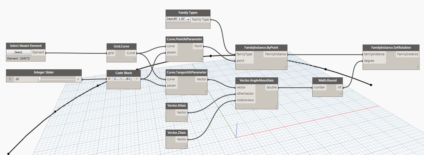
Revit Path Array With Dynamo
Ever wanted to do a path array in Revit? Well, now you can with a little help from Dynamo!
Here is a screencast I made showing how to do a path array in Revit with Dynamo. I probably should have used a spline in the video instead of an arc, because the Radial Array built into Revit is similar to an arc. So, you should definitely try this at home (or work) and use a spline instead of an arc. Also worth noting is I crashed Revit at the end of the video. This can be avoided by running the script in Manual mode. It also helps to disconnect the family instance by point, let it run with just the angle calculated, then reconnect the Family instance by point then run it again.
Path Array in Revit with Dynamo Screencast
Full Script Screen Grab:
Saturday, May 7, 2016
Dynamo, I Think We Will Get Along Well Together.

For a while now, I have been
fiddling around with Dynamo and seeing what I can get it to do for me. I am an Architect, designer, and mostly self-proclaimed Revit Aficionado
with about 13 years of experience under my belt. Until now, there were things that Revit just
could not quite accomplish, but that has all changed. With Dynamo, I was able to create the image
above with a relatively simple script I put together. This might have been possible before, but it
wouldn’t have been fun. At any rate, I
will do my best to walk through my process and show you how you can create
something like this design on your own.
I am sure a lot of you will see places I could have used a better node
to accomplish the same task, and if you have suggestions, please share in the comments.
For this, I started off with the
Default Architectural Template and launched Dynamo, which is now on the Manage
Tab in Revit 2017. My first task was to
create an ellipse. That was accomplished
with the nodes shown below:

Notice that I used the Ellipse tool
that lets you specify the plane, in this case I set it to XZ.
My next step was to make a bunch of
copies or an array of the ellipse along the Y axis, so I used the Geometry
Translate node:

In the number node attached to the
yTranslation input, you notice the code I entered as “0..200..5”. (In other words, I told dynamo I wanted a set
of numbers starting with 0 going to 200 and stepping by increments of 5).
The next thing I did was take the
arrayed ellipse geometry and rotate each one using the Geometry Rotate
node. There are several nodes for this,
so make sure to pull the same one I used below:

For the geometry input, simply
attach the output of the Geometry Translate node we had in the previous
step. For the Origin input, I added the
Point by Coordinates node, and fed the same number node I used in the previous
step. After I took the screen shot, I
realized this was unnecessary; you can simply use a single point. In other words, you don’t need to feed any
info. into the X, Y, or Z. Then, dynamo
needs to know what axis, so I told it I want to rotate about the Y Axis using
the Vector Y Axis node. The next part is
where we tell Dynamo how much to rotate each Ellipse. This is probably where I expose myself as a
Not-Very-Slick-Computer-Something Guy. I
knew I wanted the rotation of the first ellipse to be 0 and the last one
rotated at a 90, but I had to use my head to divide the total number of
ellipses by 90 to get the incremental degree of 2.25. Maybe in a later article I will have dynamo
figure the rotation for me automatically.
This would be nice, because if I adjust the amount of total ellipses I
would love for dynamo to instantly calculate the incremental rotation. If anyone has an idea for this, please
comment. It is also worth noting, that I
right clicked on the Geometry Translate node and turned off the preview of the
original array of ellipses for clarity and coolness of this view.
The next thing I did was to create
a Polysurface as shown below by adding 1 node, PolySurface By Loft, and fed the
output of the rotated geometry into the input for cross sections:

Right
now all I have is a thin shell for the surface.
I thickened that using the Surface Thicken Node:

The default thickness is 1, which works well for me, so I do
not need to feed any information into the thickness input.
The next
thing I need to do is delete the bottom half of the tunnel. There might be a better method for this, but
I used the Geometry split tool and used the XY Plane as my slicing plane. This gave me a list of 2 pieces of solid
geometry. I now needed to filter this
list by using the Get Item At Index mode to tell Dynamo which piece of geometry
I want to continue working with in my next step:


At this point, I realized this tunnel would be pretty monotonous so I decided to break it up into 5 foot segments and only import geometry for every other section. This should give a nice rhythm while still making sure the overall geometry of a rotated ellipse can still be perceived. For this, I had to go back several steps and insert a few nodes between the Geometry Rotate and Poly Surface nodes to filter the list. I really only had to introduce 2 new nodes (not counting the number nodes) but included the watch nodes to show you what the results look like since we are dealing with lists:

As you can see above, I added the List Chop node, and told
Dynamo to split the list into chunks of 2.
This left me with a set of sublists containing 2 items, except the last
item that had only 1 ellipse, so to avoid any errors, I added the Remove Item
at Index node to get rid of the last list that had only 1 ellipse.
Awesome! All done, right? No!
Unfortunately we will need to do some work on the back end to get the
correct items imported to the model. If
you switched to Revit, you might have noticed that only 1 piece of geometry is
imported. Actually, it is 2, the top and
bottom of the first ellipse. This
happened because we split our list into chunks of 2. Therefore, that filter we added before Import
Geometry that pulls items at Index 0, actually now contains a sublist of 2
items. This can be taken care of as
shown below:

The Watch
nodes were added simply to show how each list is being manipulated. The Flatten Node compresses the list and gets
rid of the sublists. Then, the Get Item
at Index node will pull only the pieces of geometry we want to import. I can switch it from simply pulling only the
Index 0 to now pull every other item starting with 0 and going to 39
(0..39..2). In other words, start with
0, end at 39, and step by 2.
When you
switch back to Revit, you can add a toposurface and make a 3D perspective view
as shown below. If you make any
adjustments to your Dynamo Script, be sure to navigate to a non-perspective
view (if you close your Dynamo script, the implied geometry goes away).:

Here are
a couple of screen shots to show the entire node. I eliminated the watch nodes for
clarity:


It is
also worth noting that if you have a toposurface with varying topography; it is
possible to use that as a cutting plane.
But, I will save that for a later post.
I hope you enjoyed this article and please feel free to leave feedback
and comments. I am very excited for the
future of Revit + Dynamo!
Subscribe to:
Comments (Atom)